CHAPTER 11
Introduction
The models in GPS-X are varied and the most comprehensive available in a wastewater treatment process simulator. In developing a model of your plant, you may require special modifications or additions to GPS-X. For example, you may want to add your own calculated variables or enter new equations. GPS-X is designed to be flexible and provides several ways to handle these special situations. In most cases you will find that the existing models provide a good foundation for customization and that with minor changes you can easily tailor the model to suit your needs. When making major changes to the process models or developing new models, it is recommended that you use the Model Developer tool that is available with GPS-X (contact Hydromantis/Hatchfor details).
This chapter covers the methods used to make modifications to the forms used in GPS-X and to add new variables and equations. The material includes an explanation of the general structure of the GPS-X software system and then outlines the various ways in which you can customize the software to suit your needs.
In general, this chapter assumes a more advanced level of understanding, both of the GPS-X system itself and other aspects of dynamic modelling and simulation. The material presented in this chapter is supported by examples rather than lists of specific procedures as in earlier chapters. The examples will help to reinforce the material and give you a more solid foundation for making your own modifications.
To complete the examples, it is helpful if you have an understanding of the following:
· Advanced Continuous Simulation Language (ACSL™)
· FORTRAN programming language
· Dynamic modelling of the unit processes in a wastewater treatment facility
ACSL is the simulation sub-system used by GPS-X. Some model modifications require an understanding of the ways in which ACSL is used to implement the model. A complete examination of the features and capabilities of ACSL is provided in the ACSL Reference Manual (Contact Hydromantis/Hatch for details).
Because the general programming language used by GPS-X and ACSL is FORTRAN, knowledge of the programming constructs in this computer language and tools for debugging FORTRAN programs may be required. Finally, since you may be making additions to the unit process models, knowledge of the fundamentals of dynamic modelling and simulation of wastewater treatment processes is important.
If you are unfamiliar with one or more of these areas, you may still be able to make the necessary modifications by following closely the examples in this chapter.
Types of Customization
There are two approaches to customization in GPS-X. The first approach involves making modifications to a specific GPS-X layout. In this case, the changes only apply to the layout itself and do not affect newly created layouts. The second approach is to create a custom library containing the changes. In this case, all layouts created using this library will make use of the modifications.
The first approach is useful if you want to add new variables or equations to a specific layout and you do not need to re-use the modifications in other layouts. For example, you may wish to create a new composite variable that is a variation on one of the existing composite variables. Methods for making the changes associated with the first approach are presented in the Customizing Layouts section of this chapter. If you inadvertently delete or corrupt these files, GPS-X can always be re‑installed.
Customizing Layouts
The second approach is useful if
you would like to change the variable names used in the GPS‑X forms
or change the default values used in the forms and then re-use
these modifications in a number of layouts. The second approach
involves modifications to model libraries and is a procedure that
requires some understanding of the structure of the GPS-X software
system. Procedures for making these kinds of changes are discussed
in Customizing Libraries section in this chapter.
GPS-X Software System
File System
The GPS-X software consists of three types of files that are stored in appropriate directories on your machine:
1. Program executable files
2. Model library and auxiliary files
3. Layout files
Program Executable Files
The program executable files are binary files that cannot be altered. They include the GPS-X executable, the ACSL executable and other secondary binary files used by GPS-X while it is running. The GPS-X executable files are stored in the \bin sub-directory in the GPS-X installation directory. The ACSL executable files are stored in the \acsl11 sub-directory in the GPS-X installation directory.
The layouts that you create are executable files; however, they are stored in the directories in which you create them.
Model Library and Auxiliary Files
The GPS-X model libraries are stored in sub-directories in the GPS-X installation directory (eg. the cnlib directory). Each of these libraries contains a binary file, gpsxm.bin that contains the lower level ACSL macros that are used to construct the process object models. This file also contains extensions to the ACSL operator set developed specifically for GPS-X. This file cannot be modified.
The GPS-X libraries contain templates for the layout files (discussed in the next section), and model auxiliary files that are specific to the unit process models built into the GPS-X software. The auxiliary files have the following general form:
· modelnme.cfg (model file)
· modelcfg.con
· modelcfg.ini
· modelcfg.dis
Where: cfg = asp, pft, pfm, pm
Here, modelname (eight alphanumeric characters maximum), and model are identifiers for each model type. The suffixes asp, pft etc., refer to the object type. The name for the .con, .ini, and .dis files are constructed by taking the first five characters of modelname and appending the 3-letter object type specification. (asp, pft, etc.). A complete list of these names is given in the Technical Reference.
The files listed above are library-dependent, so the format of the files depends on which GPS-X model library you are using (i.e. CN, CNP, Mantislib, etc.)
The modelname.cfg files contain the defining ACSL macros for the process models in GPS-X. These macros call the lower-level macros found in gpsxm.bin.
The modelcfg.con, modelcfg.ini and modelcfg.dis files are used to define the set-up of the forms accessed through each process object’s process data menu. The .con files are used to define the forms containing the parameters and constants. The .ini files are used to define the initialization forms while the .dis files are used to define the display variable forms.
Model auxiliary files are text (ASCII) files and can be edited with any text editor. By making changes to these files, you can modify initialization parameters and model constants and change the look of the menus that are displayed, and the text in those forms. You can also modify the model code, if necessary (contact Hydromantis/Hatchfor details). These types of changes involve changing the model library and will apply to all layouts created using this library (see the Customizing Libraries section in this chapter for details)
Layout Files
Layout files are specific to the layouts you prepare on the GPS-X drawing board. These include:
· layoutname.usr
· layoutname.var
· layoutname.con
· layoutname.ini
· layoutname.cmd
Where: layoutname is the file name you specify when you Save a GPS-X layout.
Layout files are used to make changes to a specific layout. You can create new variables and equations, and define your own custom data entry and display variable forms. The .usr (user) file is used to enter modelling equations. The .con, .ini, and .var files are used to define custom forms for the new variables.
Data Entry and Display Variable Forms
In GPS-X, data entry and display variable forms, such as those shown in Figure 11‑1 are created dynamically when you make a selection from the process data pop-up menu.
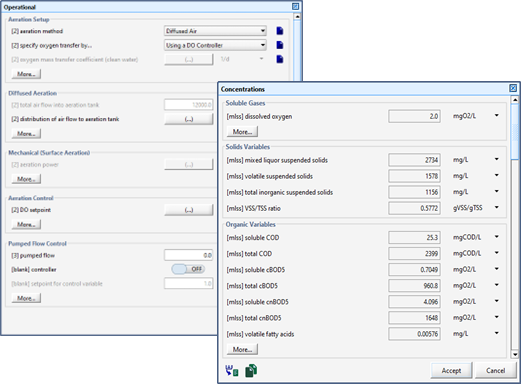
Figure 11‑1 – Data Entry (Left) and Display Variable (Right) Forms
The numerical constants and text strings used in these forms are read from the model .con, .ini, and .var files. This makes it easy to customize GPS-X to display alternative labels in the data entry and display variable forms or to add entries in these forms.
Table 11‑1 shows which file to edit for the different GPS-X forms. When you make changes to these files in a GPS-X library, the changes apply to all newly created layouts that use that library. Therefore, it is a good idea to make a copy of the library you are modifying and make changes to this new library so that the original library is left unchanged.
Table 11‑1 - Files to Edit for the Different Forms
|
To modify entries for: |
Edit the file with extension: |
|
model parameters or constants |
.con |
|
initial conditions |
.ini |
|
display variables |
.var |
Model Constants and Initialization Menus and Forms
Changes to the values of model constants and initial conditions displayed in the entry forms can be made by editing the associated .con and .ini files. The first few lines of the CN library model constants file mantipft.con, which can be found in the \cnlib sub-directory, are shown in Figure 11‑2.
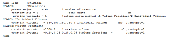
Figure 11‑2 – Example of mantipft.con File
When you display the data entry form for the physical parameters of the plug‑flow tank, the text displayed for the tank volume is shown in this file as maximum volume. Similarly, the units are displayed as m3.
Some parameters are “greyed-out” (made inactive) depending on the settings of other parameters in the menu. To make a parameter become inactive, include a semi-colon at the end of the line, followed by the parameter setting that would make the parameter active. The absence of a semi-colon at the end of the line is interpreted as meaning that the parameter should never be “greyed-out”.
If you want to change the displayed text to maximum liquid volume, then you must edit this file and enter in the new text string. This modification is shown in Figure 11‑3.
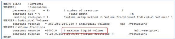
Figure 11‑3 – Modified mantipft.con File
DO NOT change the units. The algorithm calculations where these variables are used assume certain units (ie. they are the preset units displayed in these files).
The flags !MORE and !NOMORE are used to define which variables are moved to the secondary data forms accessed through the More… buttons.
If you make changes of this type to .con, .ini, or .var files in the library subdirectories, you must re-start GPS-X in order for the changes to take effect. GPS-X reads this information once during program initialization. To preserve the original files in a library directory, you should make a back-up of the files you intend to change. If you inadvertently delete or corrupt these files GPS-X can always be re‑installed.
Display Variable Menus and Forms
Display variable menus and forms are also customizable. A typical display variable menu is shown in Figure 11‑4. The text that is displayed in the Output Variables sub-menu can be changed by making modifications to the associated .dis file for that object and library.
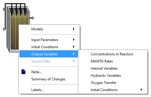
Figure 11‑4 – Output Variables in Process Menu

Figure 11‑5 – Output Variables File (mantipft.dis)
Figure 11‑5 shows the .dis file which is used to build the menu shown in Figure 11‑4.
A .dis file contains a line for each display variable point in an object. Each display variable point is associated with a physical location or flow stream on the real object being modelled. Model variables are defined for each of these points because, in general, the variable values are different.
For example, plug flow tank influent values are different from the effluent values. Each display variable point is signified by a special identifier. These are as follows:
· in – input flow stream for all objects, except pfm
· i1 – first input flow stream of pfm object
· i2 – second input flow stream of pfm object
· rin – recycle flow stream
· o – output flow stream
· p – pumped flow stream
· s – underflow stream
· g – gas flow stream from digester objects (dig)
· l – internal
The identifiers are listed first on each line of the .dis file to indicate that what follows are a list of .var files (ie. the filename excluding the .var extension) contained in the same directory that should be used to construct the Output Variables sub-menu at that display variable point.
For example, the last line of Figure 11‑5 is used to construct the menu shown Figure 11‑4. Each of the six identifiers separated by exclamation points are used to construct the name of a .var file where GPS-X gets information on how to construct additional sub-menus (if desired) and the display variable forms.
In this case, the files are:
1. compmlssvector.var
2. statevector.var
3. mantisint.var
4. cfstr.var
5. aer.var
6. ini.var
The format for a typical .var file is shown in below.
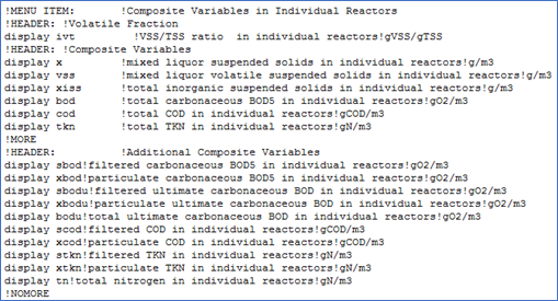
Figure 11‑6 – Output Variables Submenu File (compmlssvector.var)
By making changes to the .dis and .var files in the appropriate model library you can customize and add to the text and variable values displayed in GPS-X display variable forms. Examine the format of the existing files to gain an understanding of the structure of these forms. You can make changes to the original files, but it is best to first backup these files or copy the library files to a different directory.[12] If you inadvertently delete or corrupt these files, GPS-X can always be re‑installed.
Customizing Layouts
For every model prepared in GPS-X a special file, called layoutname.usr file, is provided for entering code. This code is inserted into the model during the build process. This provides a mechanism for defining new equations, secondary variables, modifying the initialization process and even extensive code additions to add new capabilities such as an automatic controller.
The .usr file is created for every model constructed in GPS-X and is stored in the same directory as the model layout.
A typical .usr file is shown in Figure 11‑7. The file is divided into five different sections, corresponding to the four explicit structure sections of the ACSL simulation language[13], plus an additional section for entering ACSL macro definitions. You can enter FORTRAN-language statements in these sections to define new variables using existing variables as building blocks.
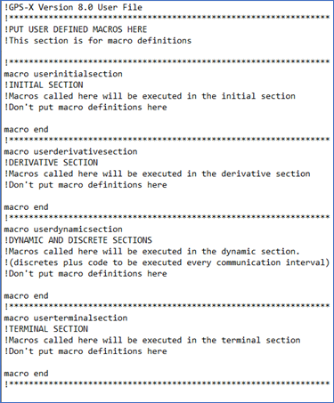
Figure 11‑7 – Empty .usr File
User Defined Macros
The user defined macros section is used to define your own ACSL macros that can be called in other sections of the user file.
Initial Section
The initial section is used for calculations that only need to be performed once before the dynamic simulation process starts. Any variables that do not change during a simulation can be calculated in the initial section.
Derivative Section
The derivative section is where you place your modelling equations (or calls to macros that set up the modelling equations). You can define differential equations here and have ACSL integrate them. Also, you can place algebraic equations in this section and have ACSL solve them. The derivative section is executed at every integration step taken by ACSL.
Dynamic and Discrete Section
The dynamic and discrete section is used for defining discrete events that happen at certain intervals and for performing output related calculations (e.g. unit conversions). For example, you can define a discrete section using the ACSL keyword, discrete, that executes code at a certain defined interval or according to a schedule.
You can perform calculations that only need to be performed at every communication interval. The communication interval is the interval at which data is transferred between ACSL and GPS-X for the purposes of recording results for output. Any statements placed in the dynamic and discrete section that are not enclosed within an ACSL discrete statement are executed at every communication interval.
Terminal Section
The terminal section is for calculations that only need to be performed at the end of the simulation.
In addition to ACSL statements, you can enter FORTRAN statements in the user file.
The .usr file provides an easy way to extend the simulation capabilities of GPS-X. The GPS-X user-interface is designed to be a generic front-end to the simulator module. Currently, GPS-X is designed to address unit process objects and models in wastewater treatment; however, it is possible to extend the process object table and model library to include other types of unit process objects and models, for example, those used in the water treatment field.
The next example looks at how a simple model can be added to the layout using these customization features.
Adding a Simple Model to a Layout – Example
Adding new models can be accomplished by entering the necessary code in the layoutname.usr, layoutname.con, layoutname.ini, and layoutname.var files.
For example, assume you wanted to model a simple first-order decay process such as:
![]()
A decay constant must first be defined so that you can set its value in the GPS-X interface. An initial condition for variable C must be specified. To define these variables, and their default values, edit the layoutname.con file so that it looks like the figure below.
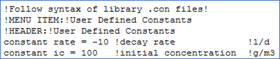
Figure 11‑8 – Example of a Simple layoutname.con File
If you want to make a more complex .con file, copy an existing .con file from one of the libraries located in the GPS-X installation directory, and use it as a template.
Next, enter the rate expression by adding the following lines in the Derivative Section of the layoutname.usr file:
dc = rate*c
c = integ (dc, ic)
The order in which you enter these lines of code is not important since the translator module automatically re-orders the equations as appropriate.
The completed .usr file should look like the figure below.
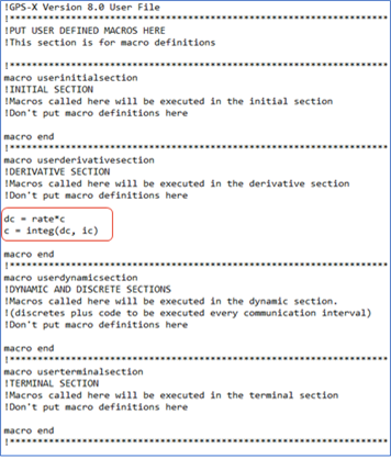
Figure 11‑9 – Example of a Simple layoutname.user File
To be able to display the new variable, C, enter the following line in the layoutname.var file:
display c !concentration !g/m3
The completed .var file should look like the figure below.
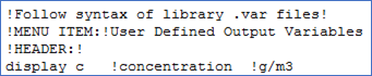
Figure 11‑10 – Example of a Simple layoutname.var File
If you want to make a more complex .var file, copy an existing .var file from one of the libraries located in the GPS-X installation directory and use it as a template.
Once these changes are made, you must re-build the model.
When you run the model, the simulator module will evaluate the equations you entered into the Derivative Section at each integration time step.
You can set up output displays using the variable c and, since it is a valid model variable, you can use it in the evaluation of secondary variables.
The variables, including constants, initial conditions and those for display, that were setup in the .con, .ini, and .var files can be accessed in the User section of the General Data menu.
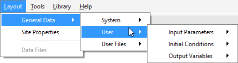
Figure 11‑11 – Accessing the User Menu
The Input Parameters item allows access to the data entry form containing the variables entered in the .con file.
The Initial Conditions item allows access to the data entry form containing the variables entered in the .ini file.
And the Output Variables item allows access to the form containing the variables entered in the .var file.
Customizing Libraries
When you make modifications to GPS-X libraries, they apply to any subsequent layout prepared using the modified library. This is significantly different from the customizations described in the previous sections, which dealt with modifications to a specific layout only.
Library customization is used when you want to make re-usable changes to the model auxiliary files.
You can also make changes to the model code, but this requires a detailed knowledge of the lower-level macros used in GPS-X. If you wish to modify the model code, contact Hydromantis/Hatch for assistance.
To successfully modify an existing GPS-X library, it is important to have some familiarity with the models in the library and in general the common basis on which GPS-X organizes these libraries. Before starting this type of customization, it is a good idea to read the material on libraries in the Technical Reference.
The steps to complete a library customization are listed below:
1. Choose the library to modify and copy the necessary files to a different directory.
2. Modify the appropriate model auxiliary files (i.e. the .ini, .con, .dis, and .var files)
3. Start GPS-X and re-build the model.
Modify the auxiliary files as discussed in Model Constants and Initialization Menus and Forms, and Display Variable Menus and Forms sections in this chapter.
Once the changes
have been made, you can start GPS-X with the new modified library
and build the model from the GPS-X interface. To use the new
library select
View > Preferences > Layout and then
choose the appropriate library from the Default Library
drop-down menu. GPS-X will automatically find all libraries in the
GPS-X installation directory.
Troubleshooting
Here are some guidelines to correct common problems that occur in model customization:
· Errors in the model library can cause GPS-X to terminate upon loading. If after creating a new model GPS-X does not start normally, carefully check that all appropriate model files exist and that they have the proper format. If you discover errors of this type, make the necessary changes and reload GPS-X. If you continue to experience problems, move the new files to another directory and try again. If problems persist, they are due to corrupt files in your library directory. Either re-copy all the library files from the appropriate library directory or if you are working within the original library directory, reinstall GPS-X from the original distribution media.
· During compilation of a layout with new user defined code, any ACSL error messages will be reported in the Building Model window (see Figure 8‑12). You will not be able to run a model until these compilation errors are corrected. See the ACSL Reference Manual, Appendix F for a list of the ACSL error messages.
Common compilation errors include the following:
Undefined variables
Check that all the new variables have been correctly declared in your model file and that any variable that is an input to the model is defined and assigned a value in the .con file
Syntax errors
The Building Model window may display the location of the error. In any case, check for typing mistakes and for lines which may exceed the 72 characters maximum.
Re-computing a variable defined as a constant
This means that one of the variables defined in the .con file has been placed on the left-hand side of an equal sign somewhere in the model file.
· Run-time errors may be reported (when the model is loaded) in the Command Window, including immediate termination of the model load process. These are due to ACSL run-time faults. Common causes for ACSL run-time problems include the following: Uninitialized variables, Division by zero.
If the model remains loaded when these types of errors occur, try displaying the values of any new variables that you have created. In the Command line of the Command Window, issue the display command by typing ‘display x2’, where x2 is the name of any new variable you have defined. Press return to issue the command. The variable and its value should be displayed in the Command Window. Repeat this process until you discover a variable which is uninitialized (equal to 5.55e 33), or equal to zero (as division by zero may be the problem). You can correct this fault by modifying the uninitialized variable in the layoutname.con file or the layoutname.ini file. If the model does not load, then it will be necessary to de-bug the model independent of the GPS-X program.